Once you go through the initial configuration of 4100 chassis and FTD bootstrap next configuration step is to setup your ASA units as Active/Standby pair or as a Cluster. Clustering on 4100 chassis is new and lets you group multiple ASAs together as a single logical device. Cluster provides all the convenience of a single device while achieving the increased throughput and redundancy of multiple devices. Over the next few posts, Transparent Cluster configuration will be covered.
Components:
FTD: 6.2
First, high-level design notes. More details can be found here.
Cluster Control Link (CCL)
In this example, we are connecting to Nexus infrastructure. Best practice dictates full physical and logical redundancy because if you loose CCL link then FTD goes offline. Your CCL throughput should also be equivalent to Data throughput. I do not see this as an issue because just basic redundancy yields 40G on CCL. You will need to use same Port-Channel (PO) on FTD modules BUT different PO’s across Nexuses (ex. PO48 for FTD01 and PO49 for FTD02). Logic extends if more chassis are added in the future. Spanning-tree is recommended for faster CCL interface recovery.

Nexus configuration is listed below. Note the MTU settings, I’ll go over the specifics in the future post.
Nexus1:
interface port-channel48
description To 4100 CCL
switchport mode trunk
spanning-tree port type edge trunk
speed 10000
mtu 9216
vpc 48
interface port-channel49
description To 4100-2 CCL
switchport mode trunk
spanning-tree port type edge trunk
speed 10000
mtu 9216
vpc 49
interface Ethernet1/15
description 4110-1 1/7 CCL
switchport mode trunk
spanning-tree port type edge trunk
speed 10000
mtu 9216
channel-group 48 mode active
interface Ethernet1/16
description 4110-2 1/7 CCL
switchport mode trunk
spanning-tree port type edge trunk
speed 10000
mtu 9216
channel-group 49 mode active
Nexus 2:
interface port-channel48
description To 4100 CCL
switchport mode trunk
spanning-tree port type edge trunk
speed 10000
mtu 9216
vpc 48
interface port-channel49
description To 4100-2 CCL
switchport mode trunk
spanning-tree port type edge trunk
speed 10000
mtu 9216
vpc 49
interface Ethernet1/15
description 4110-1 1/8 CCL
switchport mode trunk
spanning-tree port type edge trunk
speed 10000
mtu 9216
channel-group 48 mode active
interface Ethernet1/16
description 4110-2 1/8 CCL
switchport mode trunk
spanning-tree port type edge trunk
speed 10000
mtu 9216
channel-group 49 mode active
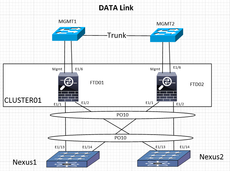
Data Link
Data interfaces will also be connected in a redundant fashion. In contrary to CCL they are part of the same PO (PO10 in this case). PO numbers do not need to match on FTD and Nexus side. On the diagram, I also have management interface connectivity depicted. Mgmt interface is used for chassis management and port E1/6 for FTD management.
Nexus configuration is listed below.
In Transparent deployment you will need to disable spanning-tree configuration on PO otherwise ports will be error-disabled due to Vlan bridging.
Nexus1:
interface port-channel10
description To 4100 Data
switchport mode trunk
switchport trunk allowed vlan x,y,z
speed 10000
vpc 10
interface Ethernet1/13
description 4110-1 1/1 data
switchport mode trunk
switchport trunk allowed vlan x,y,z
speed 10000
channel-group 10 mode active
interface Ethernet1/14
description 4110-2 1/1 data
switchport mode trunk
switchport trunk allowed vlan x,y,z
speed 10000
channel-group 10 mode active
Nexus2:
interface port-channel10
description To 4100 Data
switchport mode trunk
switchport trunk allowed vlan x,y,z
speed 10000
vpc 10
interface Ethernet1/13
description 4110-1 1/2 data
switchport mode trunk
switchport trunk allowed vlan x,y,z
speed 10000
channel-group 10 mode active
interface Ethernet1/14
description 4110-2 1/2 data
switchport mode trunk
switchport trunk allowed vlan x,y,z
speed 10000
channel-group 10 mode active
At this point network configuration is complete and you can proceed with FTD Cluster setup.
7 comments On Cisco 4100 Clustering. Part 1: Network Design
Nice one…how would you do if you have one nexus and 2 FP4100 series, where 2 links goes from each FP to the Nexus accumulating 4 links on nexus? Creating a single PO on nexus and making all those interfaces members to it would work?
Well this is what Cisco doc say:
Cluster Control Link Redundancy for Inter-Chassis Clustering
When the switch is part of a VSS or vPC, then you can connect Firepower 4100/9300 chassis interfaces within the same EtherChannel to separate switches in the VSS or vPC. The switch interfaces are members of the same EtherChannel port-channel interface, because the separate switches act like a single switch. Note that this EtherChannel is device-local, not a Spanned EtherChannel. – since my diagram has spanned Etherchannel this will not apply.
Then we’ve this statement:
Spanned EtherChannels
You can group one or more interfaces per chassis into an EtherChannel that spans all chassis in the cluster. The EtherChannel aggregates the traffic across all the available active interfaces in the channel. A Spanned EtherChannel can be configured in both routed and transparent firewall modes. In routed mode, the EtherChannel is configured as a routed interface with a single IP address. In transparent mode, the IP address is assigned to the BVI, not to the bridge group member interface. The EtherChannel inherently provides load balancing as part of basic operation. – followed by a picture with single PO on the switch.
I can tell you I’ve tried that and ports went into Err-disabled state that’s why I’ve ended up with different PO’s on Nexuses for CCL but based on Cisco doc go with a single PO.
Why does FTD require a 10Gbps management interface?
I don’t see why the onboard Mgmt Gig Copper interface isn’t just used for this purpose…
Agree, wasting a 10G port for management is crazy.
I also agree. Is this necessary???? As shauno pointed out, why can’t the on-board mgmt be used for this purpose???
What is the best way of physically connected the ASA Cluster to 2 x ISP router
Would you be able to cover Transparent FTD Clustering?
Thank you very much!
TJ